Constructing Paths
Path construction is one of the first steps in building a design. The usual procedure for constructing a path is to open the design in the Design Assistant, place a series of points in the GIS window to indicate the path, and then use the Get Path command to transfer path information from the GIS to the Design Workspace. Relationships between a path's points and the resulting work points and spans are dictated by the active path type (see Understanding Path Types).
The specific procedure for constructing a path will depend on the design's format. Bentley OpenUtilities Designer supports three graphic formats: GIS, Offline, and Template. For more information about design formats, see Working with Design Formats.
Constructing Paths and Work Locations for GIS Designs
If you are working with a GIS design, Bentley OpenUtilities Designer generates paths from trails that you draw in the GIS window. (For instructions on drawing trails with pointer devices, consult the user manual for the GIS product that you are using with Bentley OpenUtilities Designer.) Bentley OpenUtilities Designer generates work locations based on the active path type (see Understanding Path Types).
The nature of the real-world network segment that you want to represent will of course govern the number and configuration of trail points that you place in the GIS window. In addition, Bentley OpenUtilities Designer interprets trail points according to the active path type (see Path Requirements).
After you draw the trail on the map, you can use the GIS Preview command on the Actions menu to preview it and make sure the result is what you intended. If you want to redraw the trail, you can use the Undo command to delete the trail and its work locations.
The Get Path operation retrieves the spatial data from the GIS window and displays path and work location information in the Design Workspace of the Design Assistant. Work location annotations are also displayed on the GIS map.
To Construct a Path and Work Locations for a GIS Design
- From the list of designs in the My Designs view, double-click the GIS design to open it in the Design Assistant.
- In the Path Type box on the Design Toolbar, select the type of path that you want to draw.
- In the GIS window, place a series of points to create the path.
- To preview the path, choose GIS Preview from the Actions menu of the Design Assistant.
- From the Actions menu, choose Get Path.
- Or click the Get Path button on the Design Toolbar.
- To draw another trail, click Clear GIS Points on the Actions toolbar and repeat steps 2 and 3.
Constructing Paths and Work Locations for Offline and Template Designs
For designs in the Offline and Template formats, you must create paths and work locations manually using the Manual Points and Spans dialog box. This dialog box lets you specify the tap point, the number of work points in the path, and the span length. The only path type available for non-GIS designs is the Normal type, so a span is automatically created between each pair of points when you manually define the path.
Tap Points
The Tap At setting on the Manual Points and Spans dialog box lets you specify the work point(s) where the path of the offline or template design will connect with the existing network when the design is converted to a GIS design. A tap point is indicated by a "T" symbol in the list of work locations displayed in the Design Workspace. The symbol shows which work points and work spans will be associated with a tappable feature in the GIS . In the case of point locations (such as P1), the symbol indicates the physical (i.e., structural) connection point of the new design.

Four tapping options are available:
- No Tap Point-the first point of the path will be placed on an existing structure in the GIS. Note that a Normal path requires the first point to be placed on a tappable feature (usually a conductor) to ensure connectivity. Select this setting if your design will not require connectivity and you intend to transfer the design to the GIS with the Tapping Validation tool disabled (see Tapping Validation).
- Initial Tap Point-the first point of the path will be placed on an existing conductor, and the second point will be placed on an existing structure attached to the tap conductor. This second point indicates where the new segment will be physically attached to the existing network; the remaining points indicate work locations for new facilities. This is the most commonly used tapping option.
- Final Tap Point-the last point will be placed on an existing conductor, and the next-to-last point will be placed on an existing structure attached to the tap conductor (i.e., the reverse of the Initial Tap Point option). The other points indicate work locations for new facilities.
- Both Tap Points-the first and last points will be placed on existing conductors, and the second and next-to-last points will be placed on existing structures attached to those conductors (i.e., a combination of the Initial Tap Point and Final Tap Point options). The other points indicate work locations for new facilities.
Number of Points
The Number of Points setting lets you specify the number of work points that you want to include in the design. For example, if you select a value of 3, the Design Assistant will create three work points (P1, P2, P3) and two intervening spans (S1, S2)-a total of five work locations.
Keep in mind that, depending on which tapping option you select, one or more work locations will represent existing facilities, so you should make sure that you assign features to these locations whose life cycle status is In-Service. (The other attributes of an assigned In-Service feature need not match those of the existing facility because the Spatial Wizard will rely on the GIS data for the attribute values of all In-Service features in the design.) Conversely, all In-Service facilities represented in the non-GIS design should exist in the GIS before you use the Spatial Wizard to transfer the design.
Nominal Span Length
The Nominal Span Length setting lets you specify the length of the spans in the design. The default value is 200 feet. The length between spans can be changed to actual length at a later time.
To Construct a Path and Work Locations for an Offline or Template Design
- From the list of designs in the My Designs view, double-click the Offline or Template design to open it in the Design Assistant.
- From the Actions menu, choose Get Path to open the Manual Points and Spans dialog box.
- Or click the Get Path button on the Design toolbar.
- In the Tap At box, select the tapping option that describes how the new path will connect with the existing network.
- In the Number of Points box, select the number of work points that you want the new path to create.
- In the Nominal Span Length box, enter the distance (in feet) of the spans between the work points.
- Click OK.
- Assign features to each work location indicated in the Design Workspace as a tap point. Note: These features must have a life cycle status of In-Service or its equivalent. You can make this value a temporary global attribute default by clicking the Global Settings button on the Design Assistant's Standard toolbar. For more information, see Overriding the Global Attribute Values of an Active Job Default. Remember to reset this value to Proposed Install before assigning features to new work locations.
- Assign features to the remaining (new) work locations.
- Close the design and select Yes to save your changes. Note: You can reopen the non-GIS design in the Design Assistant if you want to work on it further. When you are ready to transfer the design to the GIS, change its format property to GIS and use the Spatial Wizard to complete the conversion process. For more information, see Changing the Format of a Design and Using the Spatial Wizard.
Constructing Paths and Work Locations to Retrieve Existing Features from the GIS
Existing features in the GIS can be incorporated in a GIS design when the work request calls for replacing in-service features or adding new features to a segment of the existing network. To incorporate existing features in a design, you will need to select a suitable path type and then place points in the GIS as required by the path type. The process of creating work locations for the active path type incorporates the existing features in the design and displays them in the Design Workspace.
The Design Assistant retrieves existing facilities (and any attached features if the facility is a structure) when you place points on these facilities in the GIS. A span feature is retrieved only if it is attached to a structure at both ends. (If a span feature happens to be represented in the GIS without a structure at one end, you may have to add the structure to the GIS before incorporating the span in your design, depending on how Bentley OpenUtilities Designer has been configured.)
For each retrieved feature, the Design Assistant also retrieves those attributes that are specified in the default feature definition. You can view the attribute values of a retrieved feature by right-clicking the feature and selecting Feature Editor from the shortcut menu. With the existing facilities now incorporated in your design, you can make the necessary modifications for replacing or upgrading them.
Three path types are most commonly used to pick up existing features:
A network trace can also be used to pick up an entire section of the network and its associated facilities (see Constructing Paths and Work Locations from a GIS Trace).
Except for the Start/End type, the requirements for constructing paths to retrieve existing facilities are the same as those for placing new facilities (see Path Requirements). For more information, see Start/End Path Behavior with Existing Features.
When you initiate the Get Path operation to retrieve in-service features, the Design Assistant may display a message indicating that a point is ambiguous and asking you to the clarify the choice of feature. Close the Design Assistant's message box, switch to Select mode in the GIS, and select the span feature that you want to retrieve. Then click the Get Path button again. Working in a close-up (zoom) map view can help prevent ambiguous point locations.
Start/End Path Behavior with Existing Features
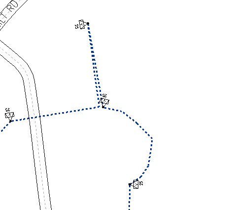
With the Start/End path type, you must place a final additional point on the span feature that you want to retrieve. In this respect, the path type behaves differently with existing features: the end point indicates a span (whereas the end point, with new facilities, indicates a new or existing structure).
For example, the Start/End path will require four points to pick up the two underground transformers and the curved segment of conductor shown in the illustration below. The first and fourth points must be placed on the span feature, the second and third points on the two transformers.
Constructing Paths and Work Locations from a GIS Trace
A native GIS trace can be used to construct a path with work locations and to retrieve existing features into the design. This operation involves these steps:
Trace Criteria
You can specify trace criteria with the Path By Trace dialog box, which opens when you select the Path By Trace setting in the Path Type box.

The Trace Type setting determines the network conditions for the trace (e.g., All, In-Service, Proposed Install, etc.). The Filter Type setting determines which facilities are retrieved from the trace and incorporated into the design (e.g., All, Primary Only, Primary and Secondary, Secondary and Service, etc.). The available settings will depend on the trace types and filter types that have been configured for your system.
In addition, you can select the Point Work Locations Only check box to include only point-type work locations in the design. If the box is not selected, both point and span work locations will be created. The Auto Assign CUs check box determines whether units will be automatically assigned. If the box is selected, the Design Assistant will assign compatible units to the retrieved features based on the current compatible unit rules for these feature types.
Trace Start Point
You can select a span, a structure, or another network feature as the start point for the trace. If a structure is the start point and it supports multiple circuits with different terminal points, an error message will be displayed and you will be asked to select an individual circuit.
If a valid start point is not selected, an error will be displayed. To be valid as a starting point for a trace, the selected feature must be either a facility in the related flow network or a structure associated with a feature in the related flow network.
Trace Stop Points
Stop conditions for network traces are usually determined during configuration, but you can also specify bounding features in the GIS prior to initiating the trace. These features will be automatically added as stop conditions for the trace.
To Construct a Path and Work Locations from a GIS Trace
- Open the design in the Design Assistant window.
- In the Path Type box on the Design Toolbar, select Path By Trace.
- From the Actions menu, choose Get Path to open the Path By Trace dialog box.
- Or click the Get Path button on the Design toolbar.
- In the Trace Type box and the Filter Type box, select the desired settings.
- To create work points only, select the Point Work Locations Only box.
- To assign compatible units to the retrieved facilities, check the Auto Assign CUs box.
- In the GIS window, place a point on the feature where you want to start the trace.
- To initiate the trace, click the Trace button on the Path By Trace dialog box.